MB 600-090
Bore Roughness Requirements
When installing KOENIG Expander® in hard base material no positive anchoring is possible. So, to attain suitable working pressures and anchorage, it is necessary to have a bore roughness of Rz = 10-30 µm. At a roughness greater than Rz = 30 µm leakage might occur. 
Roughness profile
Required roughness profile 
The ideal bore roughness for anchorage is attained by drilling with a twist drill or core drill.Undesirable roughness profile 
By reaming, a one-sided, smooth roughness profile is created. This is not desirable.
Base Material / Conditions
| Base Material of the Installation | Tensile Strength (avg.) [N/mm²] | Elongation (min.) [%] | Ultimate Strength (avg.) Rp 0.2 [N/mm²] | Hardness (min.) HB |
High Strength St. ETG-100 AISI 1144 | 1000 | 6 | 865 | 280 |
Free Machining Case Hard. Stl. C15Pb Din 1.0403 | 560 | 6 | 300 | 180 |
Cast Iron GG-25 DIN 1691 | 250 | - | - | 160 |
Ductile Cast Iron GGG-50 DIN 1693 | 500 | 7 | 320 | 170 |
Aluminium-Alloy Al CU Mg 2 DIN 3.1354 / AA2024 | 480 | 8 | 380 | 120 |
Aluminium-Alloy Al Mg Si Pb DIN 3.0615 / ~AA6262 | 340 | 8 | 300 | 90 |
Cast Al Alloy G-Al Si 7 Mg DIN 3.2371 / AA356-T6 | 300 | 4 | 250 | 80 |
- Equivalent working pressure capability can be obtained when using base materials with similar mechanical characteristics. However, the appropriate installation instructions must be followed.
- Applications for cast aluminium, magnesium alloy, other non-ferrous metals and non-metallic materials upon request
- Factors which may lower the working pressure capability are:
- anchorage principle
- bore roughness requirements
- design guidlines
- Anchorage between sleeve and base material is achieved when the sleeve is a minimum of HB = 30 greater than the base material. If the hardness difference is less, hole roughness of 10 - 30 µm is needed to achieve indicated working pressures
The security range (the difference between working pressure and Test (B) pressure) allows for uncontrollable variations. For instance, dynamic loading at 1 million cycles and a frequency of 3 - 4 Hz has shown that burst pressure Test (A) and Test (B) pressure are reduced about 20% after this point.
Design Guidelines
Wall thickness/distances from edge
As the radial expansion of the KOENIG Expander® sleeve occurs, the base material in which it will be anchored plastically deforms. The resultant strength, as well as the hydraulic pressure and temperature service conditions depending on the Expander type and characteristics of the base material, require minimum wall thickness, or distance from edge.
| | |||
 |  |  | |
| |||
Guideline values Wmin. for wall thickness and distance from edge
For KOENIG Expander® diameters d1 ≥ 4 mm: Wmin. = fmin. ⋅ d1 d1 < 4 mm: Wmin. = fmin. ⋅ d1 + 0.5 mm
| Base material | Description | 1 | 2 | 3 | 4 | 5 | 6 | 7 |
| | | | | | | | ||
Avg. tensile strength [N/mm²] | | | | | | | | |
| Min. elongation A5 [%] | | | | | | | | |
| Avg. ultimate strength Rp 0,2 [N/mm²] | | | | | | | | |
| KOENIG Expander® series | | |||||||
| MB 600 | | | | | | | | |
| MB 700 | | | | | | | | |
| MB 850 | | | | | | | | |
| SK | | | | | | | | |
| HK 55 | | | | | | | | |
| LP 900 | | | | | | | | |
| LK 600 | 0.3 | 0.3 | 0.6 | 0.5 | 0.4 | 0.5 | 0.5 | |
| LK 950 | 0.3 | 0.3 | 0.6 | 0.5 | 0.4 | 0.5 | 0.5 | |
Roundness tolerance
To assure reliable functioning of the KOENIG Expander® with regard to pressure performance and to assure leak tight sealing, a roundness tolerance of t = 0.05 mm must be held.
 | By using a double lipped twist drill, the called out hole and roundness tolerances are reached. Better tolerances, particularly for larger diameter holes, can be held by using a triple lipped twist drill |
Conicity of the bore
Within the effective sealing area of the KOENIG Expander®, the bore must be according to the data sheets. The bore lead in can be beveled up to a depth of 0.25 x d1 (LK: 0.15 x d1) because this area has no significant effect on the sealing function.
| MB series | SK series | HK series | LP series | LK series |
 |  |  |  |  |
Required Installation Lengths
 |  |  |  |  |  | ||||||||
| | | | | | | | |||||||
| | | | | | | | d1 | l2 min | d1 | l4 max | | | |
| | | | | | | | | | | ||||
| | | | | | | | | | | | | ||
| | | | | | | | | | | | | | |
| | | | | | | | | | | | | M 8x1 | |
| | | | | | | | | | | | | M 8x1 | |
| | | | | | | | | | | | | M 10x1 | |
| | | | | | | | | | | | | M 10x1 | |
| | | | | | | | | | | | | M 12x1.5 | |
| | | | | | | | | | | | | M 12x1.5 | |
| | | | | | | | | | | | | M 14x1.5 | |
| | | | | | | | | 14.0 | 8.7 | M 16x1.5 | | ||
| | | | | | | | | 16.0 | 11.5 | M 18x1.5 | | ||
| | | | | | | | | M 20x1.5 | | ||||
| | | | | | | | | M 22x1.5 | | ||||
| dN = given nominal bore/system bore size | |
| *Installation lengths MB series | |
| The required installation length (I4) min. for MB plugs is for base materials with hardness greater than HB=90. For softer materials, deeper installation is required. | |
Contact Corrosion
| Cathode | ||
| Anode |
 Large Anode Area → Low Current Density at the Anode → Slow Corrosion
 Small Anode Area → High Current Density at the Anode → Fast Corrosion
Effect of Galvanic Corrosion
The following table shows the expected galvanic corrosion behavior of KOENIG Expander®s in common base materials allowing for the relative surface areas of both metals, which influences the speed of corrosion.
| KOENIG Expander® series | ||||||||
|---|---|---|---|---|---|---|---|---|
| Base Material | MB 600 | MB 700 | MB 850 | SK | HK 55 | LP 900 | LK 600 | LK 950 |
| Steel, carbon/low alloy, plain | 2 | 2 | 2 | 2 | 2 | 2 | 2 | 2 |
| Steel, carbon/low alloy, Zn plated, chromate | 2 | 2 | 1 | 2 | 2 | 2 | 2 | 2 |
| Steel, carbon/low alloy, phosphatized | 2 | 2 | 2 | 2 | 2 | 2 | 2 | 2 |
| Nitrided or case hardening steel | behavior depends on the method used | |||||||
| Stainless steel, DIN 1.4305, AISI 303 | 1 | 1 | 3 | 3 | 3 | 2 | 1 | 3 |
| Stainless steel, DIN 1.4005, AISI 416 | 1 | 1 | 3 | 3 | 3 | 2 | 1 | 3 |
| Cast iron, GG DIN 1691, plain | 2 | 2 | 2 | 2 | 2 | 2 | 2 | 2 |
| Cast iron, GG DIN 1691, Zn plated, chromate | 2 | 2 | 1 | 2 | 2 | 2 | 2 | 2 |
| Cast iron, GG DIN 1691, phosphatized | 2 | 2 | 2 | 2 | 2 | 2 | 2 | 2 |
| Ductile cast iron, GGG DIN 1693, plain | 2 | 2 | 2 | 2 | 2 | 2 | 2 | 2 |
| Ductile cast iron, GGG DIN 1693, Zn plated, chromate | 2 | 2 | 1 | 2 | 2 | 2 | 2 | 2 |
| Dual cast iron, GGG DIN 1693 phosphatized | 2 | 2 | 2 | 2 | 2 | 2 | 2 | 2 |
| Aluminium alloy, Ws-Nr. 3.3211, AA 6061 | 2 | 2 | 2 | 2 | 2 | 2 | 2 | 2 |
| Aluminium alloy, Ws-Nr. 3.0615, ~AA 6262 | 2 | 2 | 2 | 2 | 2 | 2 | 2 | 2 |
| Aluminium alloy, WS-Nr. 3.1354, AA 2024 | 2 | 2 | 2 | 2 | 2 | 2 | 2 | 2 |
| Aluminium alloy, WS-Nr. 3.4365, AA 7075 | 2 | 2 | 2 | 2 | 2 | 2 | 2 | 2 |
| Cast aluminium alloy, WS-Nr. 3.2371, AA 356-T6 | 2 | 2 | 2 | 2 | 2 | 2 | 2 | 2 |
| Cast aluminium alloy, Ws-Nr. 3.2373 | 2 | 2 | 2 | 2 | 2 | 2 | 2 | 2 |
| Cast aluminium alloy, Ws-Nr. 3.2381 | 2 | 2 | 2 | 2 | 2 | 2 | 2 | 2 |
Key to the galvanic corrosion behavior of KOENIG Expander®s in the presence of an electrolytic medium installed in base materials per the above table:
1. Not accelerated
2. Lightly accelerated
3. Accelerated
Suggestions to prevent galvanic corrosion
Salt spray testing per DIN 50021 can be done in our lab.
Pressure Performance Tests KOENIG Expander®
Test (A) Pressure Test To Failure
In test (A) the KOENIG Expander® is subject to increasing static pressure until plug blowout occurs. These tests are done by Koenig Verbindungstechnik for functional testing during manufacturing runs. Each production lot (Batch No.) undergoes these tests.
Test (B) Temperature/Pressure Cycling
In test (B) the KOENIG Expander® is subject to a long term test simulating practical conditions. This determines the pressure which can be applied (lower limit) without plug blowout, with intermittent pressure and varying temperature.
Conditions
Temperature: 2 hours at +100 °C, 2 hours at -40 °C
series LK and LP partially 2 hours at +150 °C, 2 hours at -40 °CTemperature change: between 30 and 45 minutes Pressure: intermittent 2 minutes at 0 bar, 3 minutes at test pressure Duration: 170 h (long-term test) Drill Hole: tolerance, roundness and roughness per data sheets, plain surface distance from edge per data sheets
We emphasize the fact that the use of our sealing plugs has been tested in the above listed temperature range. Please contact us in case of deviating temperature conditions.
Quality Management
KOENIG Expander®
The first priority at Koenig Verbindungstechnik is to maintain the highest standards regarding our products, systems and service in the areas of suitability, performance, reliance, security and the environment. Koenig Verbindungstechnik has implemented an efficient and integrated quality and environmental management system, certified to ISO/TS 16949:2002 and ISO 14001. Total quality management (TQM) serves our customers via:
Clear specifications
in cooperation with our suppliers.
Precise instructions and operational sequences
for all employees.
Instructions
for test procedures.
Process control
in production and assembly.
Quality monitoring
using statistical techniques like SPC, control charts etc.
Design control
in development, project engineering and the document amendment system.
Employee training
via regular internal auditing and implementation of a quality circle.
Important:
All KOENIG Expander®s can be identified by the batch numbers on the packing label (production serial number). This batch number guarantees traceability of all quality-relevant features of production and procurement.
Anchorage Principle
The required bore roughness is directly related to the hardness and the mechanical characteristics of the base material. Depending on the combination of sealing plug and base material, anchorage takes place either by the groove profile of the expander sleeve biting into the base material or on anchorage to the surface roughness of the bore.
Note:
When selecting a KOENIG Expander® the bore roughness must always be adjusted according to the hardness of the base material.
Anchorage principle related to the base material
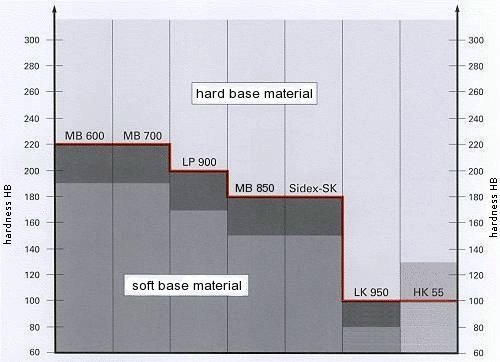
![]()
Hard base material: to achieve the allowable working pressure, anchorage to the bore roughness or the base material is required. Roughness Rz = 10 to 30 µm. ![]()
Soft base material: anchorage to the bore of the base material occurs automatically due to the serrations on the sleeve of the KOENIG Expander®. ![]()
Soft base material: anchorage is not possible with the HK series. Such combinations are not allowed for high pressure applications. ![]()
Transition zone: to achieve the allowable working pressure, anchorage to the bore roughness of the base material is required. Roughness Rz = 10 to 30 µm.
Anchorage due to plug sleeve serrations
KOENIG Expander® series MB 850 in aluminium alloy HB = 90
Anchorage due to plug sleeve serrations
KOENIG Expander® series SK in aluminium alloy HB = 90
Anchorage due to bore roughness
KOENIG Expander® series HK 55 gray cast iron HB = 160
Sufficient anchorage due to plug sleeve serrations
KOENIG Expander® series LK 950 in aluminium alloy HB = 90
Anchorage due to plug sleeve serrations
KOENIG Expander® series LP 900 in aluminium alloy HB = 90
Pressure Performance
| ||||||||||||||||||||||||||||||||||||||||||||||||||||||
Installation Instructions
Series MB
Drilled hole
- The drilled hole must be within the tolerances shown on the preceding dimensional sheets.
- The counterbored hole (d2) must be properly sized for the through hole (d3) according to the dimensional sheets.
- Holes must be round within 0.05 mm.
- With hard materials the bore roughness should be from Rz = 10-30 µm for best results.
- Longitudinal rifles and spiral grooves should be avoided. These influence the sealing effectiveness.
- The bore must be free of oil, grease and chips.
Setting procedure
 |
|
Important:
 |
|
Press
 | Assembly lines with limited travel are preferred as insertion force is difficult to control. KOENIG Expander®s are also ideal for automated installation since they offer optimal orientation capability. Small quantities or single parts can be installed with a hammer and setting tool. Installation can also be done with an arbor press. |
Installation dimensions

| MB 600 / MB 700 / MB 850 series | |||||||||||||||
| d1 (mm) | 3 | 4 | 5 | 6 | 7 | 8 | 9 | 10 | 12 | 14 | 16 | 18 | 20 | 22 | |
| S (mm) | Stroke (standard value) | 1.2 | 1.5 | 2.0 | 2.5 | 3.0 | 3.5 | 4.0 | 4.5 | 5.5 | 6.35 | 7.0 | 8.0 | 9.0 | 10.0 |
| X (mm) ± 0,2 | Position of top of ball relative to top of sleeve | 0.4 | 0.2 | 0.4 | 0.4 | 0.4 | 0.3 | 0.4 | 0.4 | 0.4 | 0.4 | 0.6 | 0.6 | 0.8 | 0.8 |
Setting forces
 a) Force with minimum bore tolerance
b) Force with maximum bore tolerance
Measured in steel with a tensile strength of Rm = 1000N/mm².
Base materials with lower tensile strengths show lower values
Plug removal
| MB 600-030 to 140 | Ball HB | ~200: | High Speed Steel Drill |
| MB 700-030 to 220 | Ball HRC | ~45: | Carbide Tipped Drill |
| MB 850-030 to 220 | Ball HRC | ~45: | Carbide Tipped Drill |
Procedure
- Expander diameter 6 mm or .250 inch:
Drill out, in one process, to the next larger diameter according to the data sheet. - Expander diameter over 6 mm or .250 inch:
Drill out in several steps with last step to the next larger diameter according to the data sheet. - Clear chips, remnants of the sleeve, and oil and grease from the bore.
- Install a new KOENIG Expander®.
- Note: After plug removal always use the next larger size plug.